
My Mother’s Binary Clock
When I was a boy (ca. 1978) I was an electronics hobbyist. I’d build some bizarre circuit on a breadboard and show it to my mom, who was enthusiastic, but didn’t know what it was.
She asked me to build her something “that was in a box” so she could show it to friends and relatives when they came to visit. At about that time we were doing an electronics segment in my high school shop class and had the chance to build a project from a kit. I shared the catalog with my mother and together we picked out the Graymark Binary Clock.
It was a hit with her and until the day she died she proudly displayed her Binary Clock on the mantle. Visitors would invariably ask about it and she’d teach them to read binary and tell the time.
Sadly, a couple of years before she passed, the clock fell from the mantle and the circuit board cracked. I inherited the clock and decided that I’d rather upgrade it than merely repair it.
Here’s the video on the final project.
The Original Clock
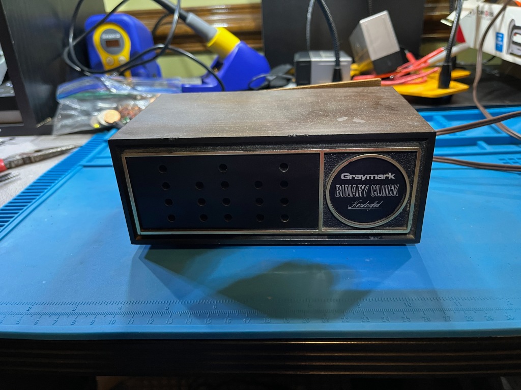
Here is the original clock. It may be hard to see from here, but there are 18 LEDs. The first column is for the hours, the next two for the minutes, and the final two for the seconds.

You can decipher the time from these instructions on the bottom of the clock.
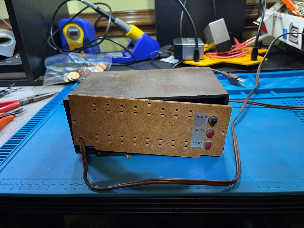
The “HOLD”, “SLOW”, and “FAST” buttons on the back allow you to set it.

Here is the offending / broken circuit board. The crack was along the entire board and at a point where the board was weakest because of the power supply’s installation. I had tried a repair several years ago for my mom, but it wasn’t a permanent fix.

Here is the LED display board. The LEDs were almost all intact. One LED had failed. I didn’t have an exact match, so I used a close duplicate. I’ll explain that below.
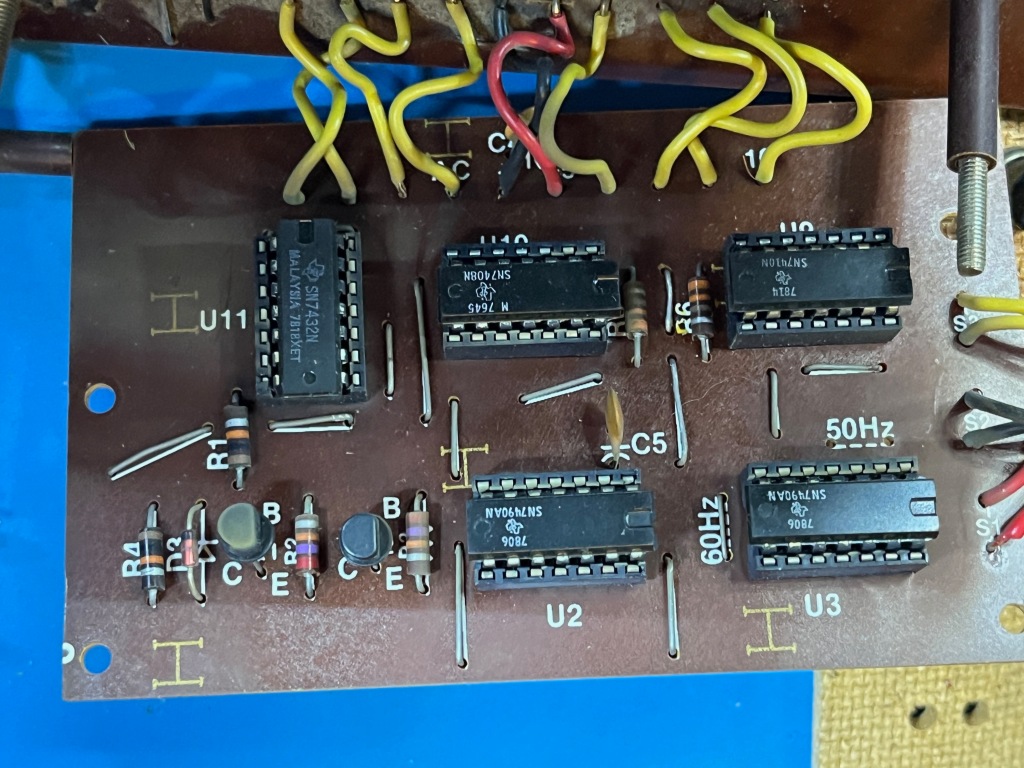
This is the “heartbeat” circuit board which delivers the one-per-second “pulse” to the clock. ICs U2 and U3 are 7490’s – which are 4-bit BCD (Binary Coded Decimal) counters. They are used to divide-down the frequency delivered by the AC transformer from 60Hz (or 50Hz) down to 1 cycle per second. In the USA, the AC frequency is 60Hz but in the UK it was 50Hz. You can see some jumpers on the board for either 60Hz or 50Hz. These were used in conjunction with U11 (7432 Quad-OR gate) to set the divider to either 60 or 50.
The wires on the right came from the push buttons. The “HOLD” button (black) stopped the clock by disconnecting the “heartbeat”, the “SLOW” button (yellow) increased the pulse by a factor of 10, and the “FAST” button (black) increased the pulse to 60Hz (or 50Hz). This allowed the user to set the clock’s time.
The other ICs (U9/U10 and U11) are 7408’s and a 7432. These are quad NAND and OR gates (respectively) and are used to handle the decade counter logic for 60/50 Hz and fast/slow counting.
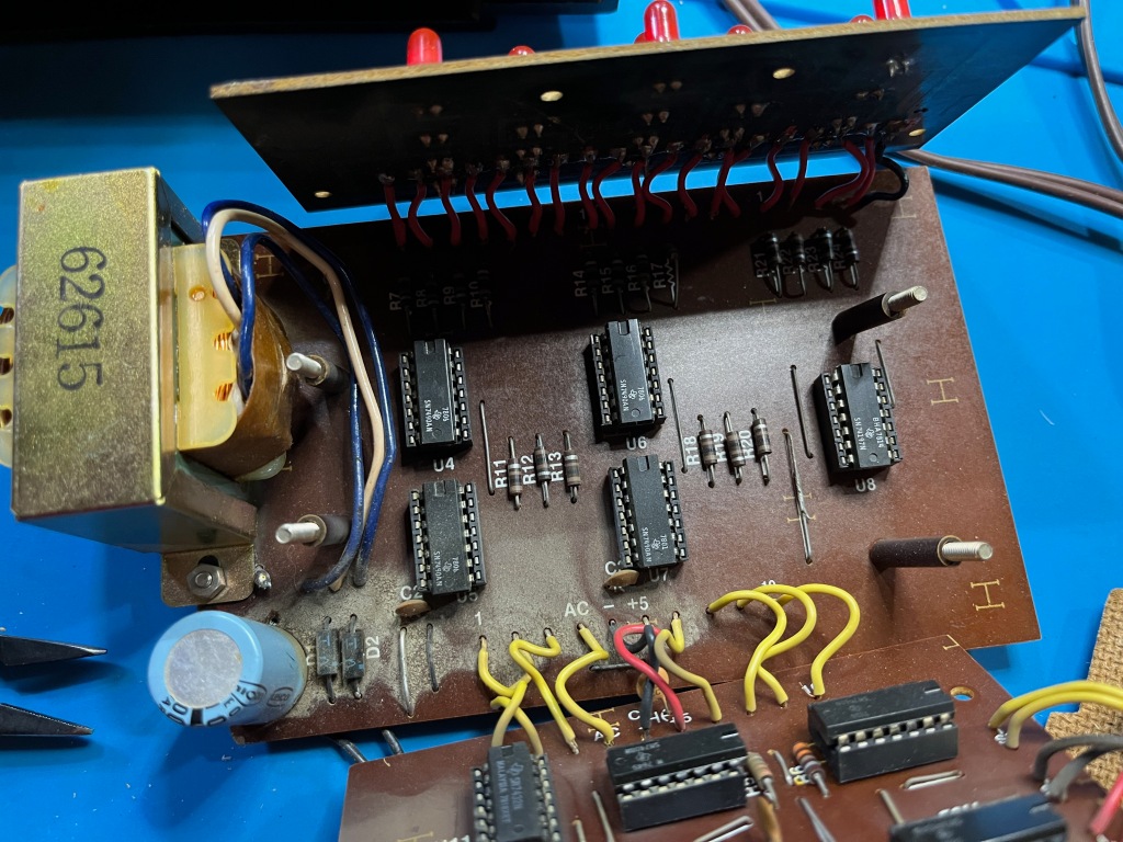
This is the main logic board. It receives the clock pulses from the “heartbeat” board. The heartbeat is sent to U4 – a 7490 BCD counter – which increments from 0 to 9 once per second. The 4-bit output drives the “seconds” LEDS. You can see the 110-ohm resisters that feed the LEDs. These are current-limiters so the LEDs don’t get too much current and get blown out.
U4 sends a signal to U5 (another 7490) when it overflows from 9 back to 0. U4 then counts from 0 to 5 for the tens-of-seconds. It then drives the tens-of-seconds LEDs through another bank of 3 110-ohm resisters. U5, upon overflow sends a signal to U6 (7490) which counts the minutes, which drives U7 (7490) which counts the tens of minutes. Finally, the overflow from U7 drives U8 which counts the hours. U8 is a 74197 binary counter. It is configured to count from 1 to 12 and reset back to 1 for the hours. Like the other counters it drives the LEDs through a set of 110-ohm resistors.
This is a fairly straightforward project. And it deftly demonstrates how digital clocks work internally. If you wanted to, you could add 7447 ICs to drive 7-segment displays and you’d have a classic digital clock. Using discrete LEDs, though, creates a Binary Clock which is a simpler display, and quite the conversation piece.
The Upgrade Project
My goal is to replace the power supply and logic boards with a Raspberry Pi Pico W. I want to maintain all the functionality of the original Binary Clock, plus some new features:
- Original Case
- Original LEDs
- Original HOLD, SLOW, and FAST switches
- NEW: Setting the clock with an iOS Blue Tooth App
- NEW: Setting the clock from the WWVB Atomic Clock
- NEW: Setting the clock using the Internet Network Time Protocol (NTP)
- NEW: Store settings on the persistent Flash store
Raspberry Pi Pico W
The Raspberry Pi Pico (aka RPi Pico or just Pico) is a single board microcomputer that has a RP2040 (32-bit dual ARM Cortex-M0+ microcontroller) at its heart. It also has 256KB of RAM and 2MB of Flash memory as well as 26 GPIO (General Purpose Input / Output) pins. It also has a bunch of other on-board features which I won’t be using.
The Raspberry Pi Pico W – has an additional IC that adds both WiFi and Bluetooth capabilities.
The Pico retails for about $4USD and with the WiFi/Bluetooth chip, $6USD. It’s an amazing value for so much computing power.
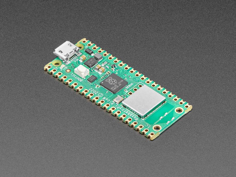
The board runs on 3.3 volts and can tolerate a supply voltage of up to 5 volts. This is usually supplied through a mini-USB port connected to a laptop or dedicated power brick. When connected to a laptop one can download software to the Flash memory, or communicate with a downloaded program through the serial connection.
As a microcontroller, there is no proper operating system for the RPi Pico. But there are several on-board programming languages that can be stored in the 2MB Flash drive. While CircuitPython from AdaFruit is arguably the best Python implementation for the Pico, I’ll be using MicroPython from the Raspberry Pi Foundation.
(As of this writing [7/16/2023] CircuitPython from AdaFruit has no implementation for the on-board Bluetooth controller. RPi Foundation’s MicroPython added such support in March 2023. In conversations about this on AdaFruit’s GitHub, they appear to favor their own add-on Bluetooth board with no plans to support the on-board Bluetooth. So, I’m opting for the MicroPython implementation https://github.com/adafruit/circuitpython/issues/7693).
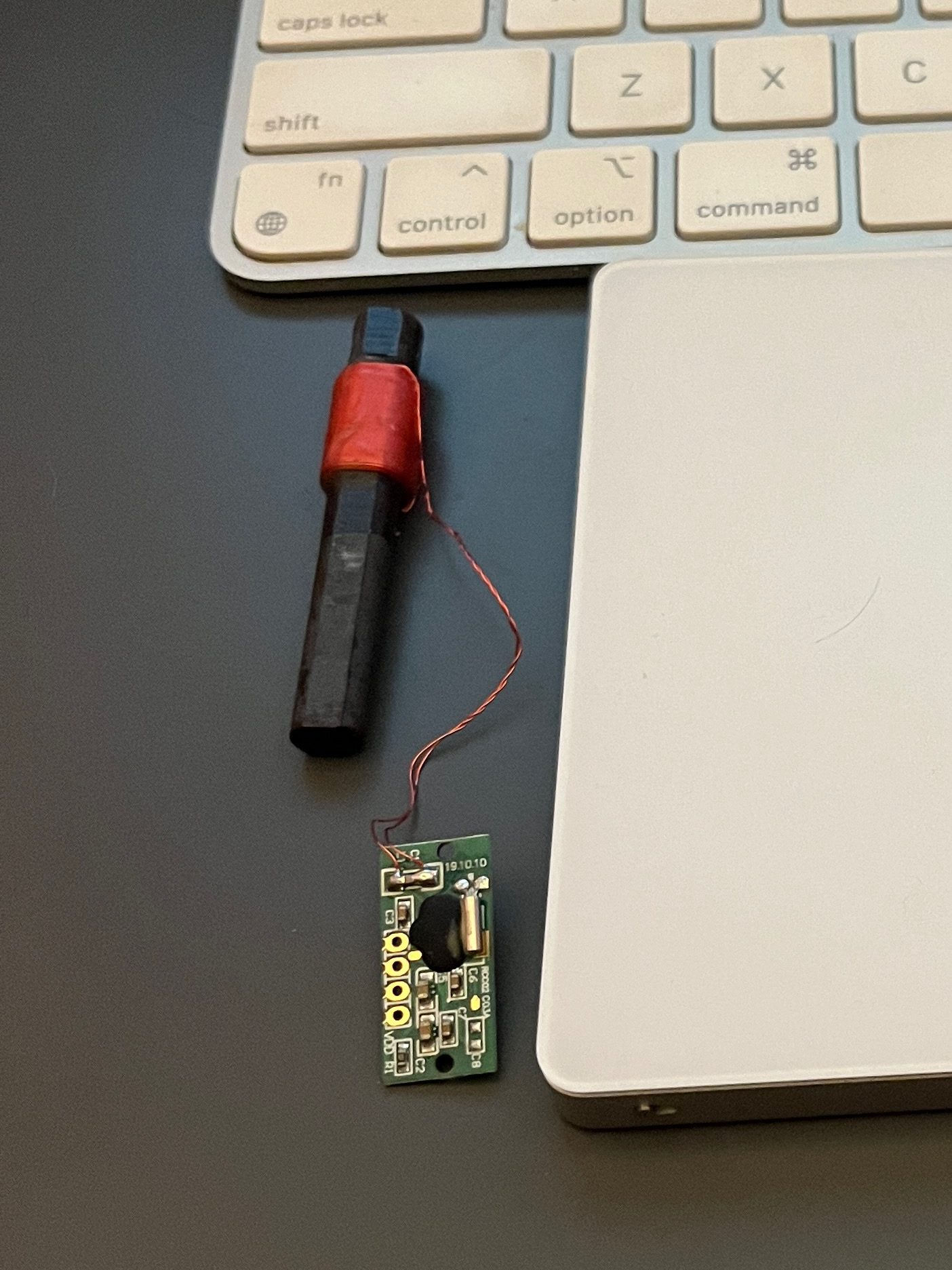
Salvaging the LEDs

The first step was to remove the LED panel and test each LED. I wanted the LED panel to be removable, so I installed a ribbon cable and appropriate connectors. Since I was prototyping on a breadboard, the 2.54mm pin headers were used. I wired the LEDs in three groups of ribbon – hours, minutes, and seconds. I also salvaged all the original 110-ohm resistors to act as current limiters.
Sadly, one of the LEDs was blown out. I didn’t have a ready supply of the exact matching LEDs, so I found one that was close to the same size. Since the replacement LED was brighter than the original, I wired a 10K-ohm resistor in place of the 110-ohm resistor. The difference is almost unnoticeable.
From Breadboard to Perfboard
The entire project was prototyped on a Breadboard. I picked up a very nice perfboard that matched the pinout of the breadboard from my local “maker shop” (http://HackRVA.org) and transferred the lot to the perfboard. The LEDs are tied to GPIO pins 0-17 and the three switches on on GPIO pins 18, 19, and 20.

I was able to use battery power for the interim. Upon testing, the board only lasted 1 day on batteries – so I’ll clearly have to wire a plug for an external power brick.

I also salvaged the switches from the back of the unit and wired them to the perfboard. The switch contacts were pretty dirty and needed cleaning. I didn’t want to risk more damage by trying to disassemble them. So I soaked them in 100% Isopropyl Alcohol and blew them dry with compressed air. After a couple iterations, the contacts were “clean enough”.
I spent a little time shining up the case using my favorite cure-all: WD-40.
Programming and Bluetooth Control
One thing that was always a hassle with the original binary clock was setting the time. While I was able to reprogram the clock (in MicroPython) to use the “HOLD”, “SLOW”, and “RESET” buttons, I wanted a better interface.

and wall-mounted 43″ Monitor
I used my “Slabtop” MacBook Air to download MicroPython to the Pico and program it. I programmed the Bluetooth Low Energy (BLE) chip to connect to an external app. I used MicroPython’s “bluetooth” library and a couple example modules from their GitHub repo (ble_simple_peripheral and ble_advertising) to configure the BLE. Then, I was able to connect to the clock using AdaFruit’s “BlueFruit Connect” app for iOS.
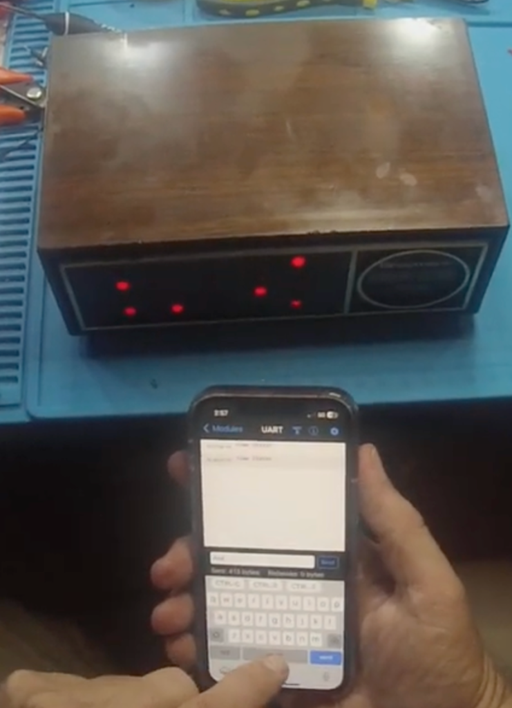
I created a mini-CLI (Command-Line Interface) with a simple “verb/object” language to control the clock:
time <HHMMSS>(set the time)debug <on/off>(turn on debug mode)delay <ms>(in debug mode, set the delay between time clicks for fast time cycling)
I’ve uploaded all the test and final code to my GitHub repo: https://github.com/devcybiko/rpi-binary-clock
Conclusions
I’m very happy with the results. I still have a few details to iron out including the power supply and the WWVB Atomic Clock settings. But for now, this feels like I’ve restored and upgraded my mom’s favorite hardware project. I’ll update this page when I add more features.
